What is a Data Flow Diagram (DFD)?
When it comes to system analysis, software engineering, and business process modeling, it is very important to understand how data moves through the system and how the system manages it. There are various ways and tools that are used to understand the data flow within the system. One of the most effective and widely used tools for visualizing the movement of data is the Data Flow Diagram (DFD).
| Key Takeaways: |
|---|
|
This article explores what a Data Flow Diagram (DFD) is, why it is important, its history, core components, different types and levels of DFDs, rules and best practices, real-world use cases, advantages, and limitations. It also discusses how DFDs compare with other modeling techniques.
What is a Data Flow Diagram (DFD)?
A Data Flow Diagram (DFD) is a graphical representation used to illustrate the flow of data within an information system or a business process.
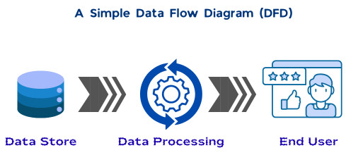
A DFD shows how data enters a system, how it is processed, where it is stored, and how it exits the system.
A simple DFD is shown below:
- What is the source of the data, or where does the data come from?
- What happens to the data, or how is the data processed?
- Where is the data stored?
- Where does the data go next?
You might think DFDs are like flowcharts that depict the flow of a program. However, this is not the case. Flowcharts focus on the control flow of the program and decision-making logic. DFDs, on the other hand, focus only on data movement and transformation.
DFDs are not bothered about program logic, algorithms, or timing; instead, they emphasize what data is processed, not how the processing is implemented.
A DFD acts as a blueprint for the system. It simplifies complex systems into easy-to-understand, hierarchical diagrams that can be used to analyze, improve, or design system workflows.
- DFDs show the “what” rather than the “how” (no control flow, loops, logic, or decisions). They help identify bottlenecks and improve system efficiency.
- DFD has various components as follows:
- External Entities: Sources or destinations of data (e.g., customers or data stores).
- Processes: Actions that transform data (e.g., normalization of data).
- Data Flows: Arrows indicating the movement of data from one component/entity to another.
- Data Stores: Repositories where data is kept (e.g., databases).
- Graphical symbols are used to illustrate the paths, processes, and storage repositories to indicate data flow across the system (from entry to exit).
- DFDs are structured in levels that represent details as Level 0 for a high-level view, followed by Levels 1, 2, and above for increased detail.
- DFDs are widely used in business analysis, system development, and software engineering to streamline communication between technical and non-technical stakeholders.
- This visual representation is used by professionals to identify ways to improve the efficiency and effectiveness of existing systems and processes, and create new ones.
History of Data Flow Diagrams
DFDs first came into existence as early as the 1970s, when software engineers Larry Constantine and Ed Yourdon introduced them in their book, “Structured Design”. In this book, they used DFDs to depict the movement of data within a software system, instead of focusing on software procedures.
Computer scientists Tom DeMarco, Chris Gane, and Trish Sarson developed standardized data flow symbols and notations that are still being used.
In the beginning, DFDs were used only in software engineering. However, initially, after discovering their value for understanding and improving business processes and workflows, business professionals began using them.
Unified Modeling Language (UML) was introduced in the 1990s. With this, software programmers stopped relying exclusively on DFDs for software engineering. UML diagrams were used instead, as they provide an intricate, detailed view of structures and behaviors in complex object-oriented systems.
As of today, DFDs are used primarily as complementary tools to UML diagrams and flowcharts, providing high-level system overviews during software development.
Why are Data Flow Diagrams Important?
DFDs play a crucial role in both technical and non-technical environments. They are easy to understand and have the ability to simplify complex systems. This makes them all the more important in software engineering and business processes.
DFDs use simple symbols and minimal technical jargon, making themselves accessible to managers, analysts, developers, and end users alike.
- Gain Clarity: DFD is represented visually with simple symbols and labels, providing a clearer understanding of complex systems than monotonous paragraphs of descriptive text.
- Analyze Systems: DFDs clearly represent the relationships and interactions among the components of a system or process, making system analysis easier.
- Identify Problems: Using DFDs, system design problems such as bottlenecks, inconsistencies, redundancies, and others can be isolated. It is also easier to detect inefficiencies or missing data flows using a DFD.
- Improve Processes: Analysts can use DFDs to visualize ways to optimize data flows to accelerate and improve business processes.
- Drive Collaboration: DFDs provide a shared point of reference for stakeholders across the organization, promoting effective communication and collaboration. In doing so, it effectively bridges the gap between technical teams and business stakeholders.
- Create Documentation: DFDs provide a clear, visual system documentation by capturing essential information such as the sequence, requirements, and processes of a data flow.
- Protect Data: DFDs address potential data security risks by clearly indicating where sensitive information enters and exits a system.
What are the Core Components of a DFD?
Every Data Flow Diagram is built using four fundamental components. Understanding these elements is essential for creating and interpreting DFDs correctly. The main components of a DFD are shown below:
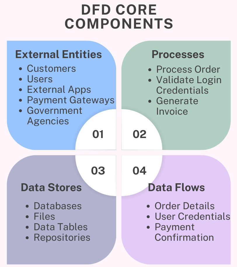
External Entities
External entities are the starting and ending points for the data flow or sources and destinations of data in a DFD. They exist outside the system boundary and are not part of the system, though they interact with the system.
In a DFD, external entities are placed on the edges to represent the input and output of information to the entire system or process.
- Customers
- Users
- External applications
- Payment gateways
- Government agencies
External entities are usually represented by rectangles and are also known as terminators, actors, sources, and sinks.
Processes
A process represents an activity that processes the incoming data (input) to generate an output (outgoing data). It may contain details of activities such as data manipulation, computation, calculation, sorting, redirection, or validation within the system.
- Process order
- Validate login credentials
- Generate invoice
- Verify credit card payment.
Processes are typically shown as circles or rounded rectangles and should be labeled with a verb-noun phrase.
Data Stores
A data store represents a location where data is stored for later use. It can be a physical or a digital storage location.
- Databases
- Files
- Data tables
- Repositories
Data stores are commonly represented using open-ended rectangles or parallel lines.
Data Flows
Data flows represent the way data moves between entities, processes, and data stores. They are routes that the data takes as it travels between external entities, processes, and data stores. Data flows always originate from or terminate at a process.
- Order details
- User credentials
- Payment confirmation
- User authentication
Data flows are depicted using arrows, labeled with the name of the data being transferred.
Symbols Used in Data Flow Diagrams
- Yourdon and Coad
- Gane and Sarson
Despite minor visual differences, both these systems use the same fundamental concepts and components. The following table shows the symbols used in a DFD:
| Component | Symbol Description | Symbol Notation |
|---|---|---|
| External Entity | Rectangle | |
| Process | Circle or rounded rectangle | |
| Data Store | Lines or Open-ended rectangle | |
| Data Flow | Arrow |
Note that the consistency in notation is more important than the specific style chosen.
What are the Different Levels and Types of Data Flow Diagrams?
DFDs are typically developed in multiple levels, starting from a high-level overview (level 0) and progressing to more detailed views. As DFD progresses to higher levels, it shows more details of the system or process.
This layered approach using levels begins with a simple, high-level view and becomes more complex as lower-level DFDs dive deeper into processes and subprocesses.
Here are the levels in a DFD that are typically used:
Level 0 (Context Diagram)
This level is the simplest and most basic level and is also called a “context diagram”. At level 0, DFD visualizes the entire system as a single process. Everyone, regardless of technical skill or job role, should be able to read and understand a DFD at level 0.
- Level 0 DFD shows the system as one process.
- It displays interactions with external entities.
- DFD does not show internal data stores or subprocesses.
- Defining system boundaries.
- Clarifying system scope.
- Identifying external stakeholders.
Example
As an example, let us take a “Teacher Feedback System”. Here, the student entity will provide feedback for the teacher, and the principal will be able to view that feedback. A level 0 DFD for this system is shown here:
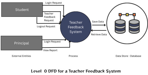
As shown, this is a high-level diagram of the teacher feedback system, where the entire feedback system is represented in a single process.
Level 1
A level 1 DFD breaks down the single process from the content diagram (level 0 DFD) into multiple subprocesses. It explores the component parts of the high-level process in more detail.
- The Level 1 DFD shows the major system functions.
- It introduces data stores.
- Level 1 DFD provides more detail than the context diagram.
Each process in Level 1 corresponds logically to the main process shown in Level 0.
Example
Continuing with the Teacher Feedback system, in level 2 DFD, the feedback system module will be split into subprocesses as shown in the DFD below:
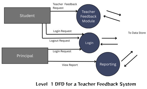
As seen in the above image, the Teacher Feedback Module is divided into subprocesses: Teacher Feedback, Login, and Reporting.
Level 2
Level 2 DFDs provide even more granular detail by decomposing processes from Level 1 into subprocesses. The decomposition can further continue into Level 3 or beyond as needed. This also shows interactions of subprocesses with data flows and data stores.
- Provide a detailed functional understanding of the system.
- Support system design and development.
- Clarify complex processes.
In reality, not all systems require deep decomposition; the level of detail depends on system complexity.
Example
Level 2 DFD will further provide detailed functionality of the Teacher Feedback System. This is depicted in the DFD below:
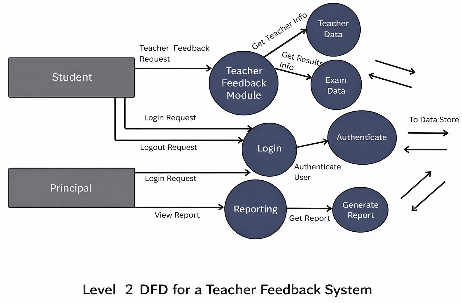
In the above example, the Teacher Feedback Module is further divided into subprocesses, Teacher Data, and Exam Data, and it fetches the teacher’s info and exam results data related to that teacher. Similarly, the Login module calls the subprocess Authenticate to authenticate the user.
The reporting module will call the generate report module to get the report for the principal to view.
Level 3
DFDs are intended to be simple and easy to understand. It is unusual to go beyond level 2 for most of the systems. However, some highly complex systems might need to elaborate on details at Level 3, which maps every single aspect of a data process or system.
Types of Data Flow Diagrams
- Logical DFDs
- Physical DFDs
Logical DFDs
A logical DFD provides a high-level view of the data flows that are required to perform business or system processes. It does not go into technical or implementation details. The focus of logical DFDs is primarily on the data needed and its movement through the process to complete a specific business objective.
Logical DFDs often represent business activities such as order fulfillment at a warehouse, patient intake at a hospital, or a customer making an online purchase.
Physical DFDs
A physical DFD focuses on the system’s physical aspects and visualizes the implementation of a system or process, including the required software, hardware, and files. They focus on the underlying technologies, procedures, and operations of a system or process.
Physical DFDs are often used to represent complex systems and workflows, such as the secure transmission of electronic health records within a hospital system or the inventory management at a warehouse using supply chain software.
Rules and Guidelines for Creating DFDs
Every DFD must follow certain rules to ensure accuracy and consistency. The key rules and guidelines that are to be followed for creating DFDs are:
- Every process and data store must have at least one input and one output.
- Data cannot move directly between two data stores.
- Data cannot move directly between two external entities.
- Data cannot move directly from an external entity to a data store.
- Data flows must be named clearly.
- Processes should be labeled using verb phrases.
- Data stores and entities should use noun phrases.
- DFDs at different levels must be balanced, meaning the input and output data flows of a process must match across levels.
- Data stores cannot be connected directly to external entities.
- External entities can transmit data to a process, but cannot transmit data directly to a data store.
Real-World Applications of Data Flow Diagrams
DFDs are used to visualize, analyze, and optimize how data flows through information systems in real-world applications. They are heavily used in finance, healthcare, and e-commerce industries to design software, map business processes, ensure regulatory compliance, and manage data.
Software Development
In software development and engineering, DFDs are used in system requirement analysis, application design, and API data flow visualization. They identify input/output data points, define API endpoints, and troubleshoot, visualizing data movement within applications to improve system design.
Business Process Modeling
Model workflows such as logistics, onboarding, ordering, and financial transactions using DFDs. They help identify bottlenecks, inefficiencies, and unnecessary steps.
Education
In the education field, DFDs are helpful in teaching system analysis concepts and understanding information systems.
Financial Management & E-commerce
DFDs map data flows for secure payment processing, online ordering, and transactional data management, which are crucial for accuracy in the finance and e-commerce industries.
Healthcare and HR Systems
In healthcare and HR systems, DFDs manage the secure, accurate flow of sensitive patient or employee information between different systems.
Marketing Analytics
Data movement from customer touchpoints, such as social media and website analytics, into CRMs can be visualized using DFDs to improve marketing strategies.
Compliance and Auditing
DFDs are crucial for tracking data flows to ensure compliance with regulations such as GDPR and HIPAA, and for visualizing data movement in cloud ecosystems for security auditing. They also help with security reviews and regulatory documentation.
Advantages of Using Data Flow Diagrams
- Clarity: DFDs simplify complex systems by providing a visual roadmap of how data flows from source to destination, including transformations and storage, offering greater clarity than verbal or written descriptions.
- Improved Communication: DFDs use simple, intuitive notation, allowing both technical and non-technical stakeholders (users and designers) to easily understand, discuss, and analyze system processes.
- Better System Design: DFDs map the entire system and help identify bottlenecks, redundant steps, and potential improvements, improving overall efficiency and security.
- Defining System Scope: DFDs clearly define a system’s boundaries, clarifying what is included within the system versus what is handled by external entities.
- Technology-independent: DFDs focus on the what (logical flow) rather than the how (physical implementation), allowing the design to remain flexible during early stages and independent of technology.
- Documentation Value: DFDs serve as long-term system reference and essential system documentation, allowing for top-down decomposition of complex systems into smaller, more manageable sub-processes.
Limitations of Data Flow Diagrams
- No Control Flow or Timing Details: DFDs focus solely on how data moves (logical flow) rather than the order of operations, timing, or performance constraints, making them unsuitable for representing complex, sequential logic.
- High Complexity and Size: When the system is large and detailed, DFDs can become extremely complex, messy, and difficult to manage or understand.
- Difficulty in Maintenance: DFDs require regular, time-consuming updates when system requirements change. If not maintained properly, they often become outdated, reducing their usefulness in agile environments.
- Lack of Physical Implementation: DFDs focus on functional logic and ignore physical aspects such as hardware, specific software, or user interface details.
- Potential for Misinterpretation: DFDs are simple and have an abstract nature, due to which they can be misunderstood by users, leading to incorrect assumptions about the system.
- Ambiguity in Data Volume: The volume or frequency of data being transferred between components is not represented by DFD, leading to ambiguity.
Best Practices for Creating Effective DFDs
- Start with a Context Diagram: a single, high-level view that treats the entire system as a single process, showing inputs and outputs from external entities.
- Decompose Gradually: Move from Level 0 to Level 1, 2, and beyond, only as and if needed. Do not over-complicate the diagram at higher levels.
- Keep Diagrams Simple and Readable: Limit each diagram to 6-9 processes to ensure they are easily readable.
- Use Consistent Naming Conventions: Name entities and data stores using nouns and processes using verb-noun phrases (e.g., “Authenticate User”).
- Use Consistent Notations: Use either Yourdon & DeMarco (circles) or Gane & Sarson (rounded rectangles) notations to represent DFD core components consistently throughout all levels.
- Validate Diagrams with Stakeholders: Ensure the DFD accurately reflects the current system by validating it with all stakeholders, including users and developers.
- Avoid Unnecessary Detail: Create DFDs without including any unnecessary details. Design them to be to the point to avoid complex DFDs.
- Ensure Balance Across Levels: Data flows entering/exiting a parent process must match those in the corresponding, more detailed child diagram.
- Use Specialized Software: Use tools like Lucidchart, Draw.io (diagrams.net), Microsoft Visio, or Figma to maintain consistent shapes and improve collaboration.
Conclusion
As discussed and demonstrated in this blog, a Data Flow Diagram (DFD) is a powerful and time-tested tool for visualizing the data flow through a system. They provide a clear and intuitive understanding of system functionality without focusing on implementation details.
Whether you are a software professional designing systems, a business analyst defining requirements, a data professional mapping pipelines, or a student learning system analysis, DFDs offer immense value. When used correctly and combined with other modeling techniques, DFDs become an essential component of effective system design and documentation.
In an increasingly data-driven world, the ability to clearly map and understand data flow is not just useful; it is critical.
Additional Resources
- What is Code Optimization?
- What Is Data Visualization?
- SQL Database Concepts: Fundamentals Every Developer Should Know
- Difference between YAML and JSON
- What is Software Architecture?
- Cohesion vs Coupling
- What are the Qualities of a Good Software?
Frequently Asked Questions (FAQs)
- What is the difference between a DFD and a flowchart?
There are subtle differences between a DFD and a flowchart. While a DFD focuses on data movement, a flowchart focuses on process flow and decision logic. Unlike flowcharts, DFDs do not show control flow, conditions, or loops; they show only how data enters, flows through, and exits the system.
- Are DFDs still relevant today?
Yes, they are. Despite modern architectures such as microservices and event-driven systems, DFDs remain valuable for understanding data flow, particularly for security reviews, compliance audits, and system documentation.
- Can DFDs be used for security and privacy analysis?
Absolutely. DFDs are widely used to:
- Identify sensitive data flows
- Perform threat modeling
- Reveal potential data leakage points.
- Support compliance with regulations like GDPR or HIPAA
- How detailed should a Data Flow Diagram be?
The level of detail in DFD depends on the objective. High-level DFDs are best for stakeholder communication, while lower-level DFDs are useful for developers, testers, and security teams. Each level should remain clear and easy to understand.
- Who typically creates and uses Data Flow Diagrams?
The following stakeholders commonly create and use DFDs:
- Business analysts
- Software architects
- Developers
- Testers and QA engineers
- Security and compliance teams
|
|